


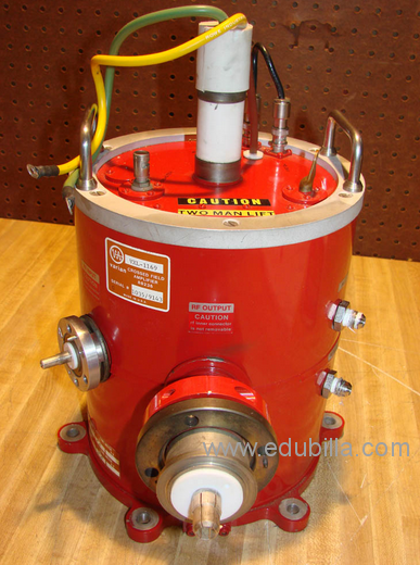
A crossed-field amplifier (CFA) is a specialized vacuum tube, first introduced in the mid-1950s and frequently used as a microwave amplifier in very-high-power transmitters.
History
Raytheon engineer William C. Brown's work to adapt magnetron principles to create a new broadband amplifier is generally recognized as the first CFA, which he called an Amplitron. Other names that are sometimes used by CFA manufacturers include Platinotron or Stabilotron.
A CFA has lower gain and bandwidth than other microwave amplifier tubes (such as klystrons or traveling-wave tubes); but it is more efficient and capable of much higher output power.
Peak output powers of many megawatts and average power levels of tens of kilowatts can be achieved, with efficiency ratings in excess of 70 percent. Their current use is in ground stations for TVRO broadcasting and Deep Space telecommunications networks.
Procedure
The electric and magnetic fields in a CFA are perpendicular to each other ("crossed fields"). This is the same type of field interaction used in a magnetron; as a result, the two devices share many characteristics (such as high peak power and efficiency) and they have similar physical appearances. However, a magnetron is an oscillator and a CFA is an amplifier; a CFA's RF circuit (or slow-wave structure) is similar to that in a coupled-cavity TWT.
The CFA has the useful property that when power is shut off, the input simply passes to the output with very little loss. This avoids the need for RF bypass switching in the event of failure.
Two redundant CFAs can be connected sequentially, with only one powered; if it fails, power can be removed from the primary tube and applied to the secondary as a backup. This approach was used on the S-band downlink transmitter on the Apollo Lunar Module where high efficiency and reliability were needed.
A large negative voltage is placed on the green electrode in the center, and a large magnetic field is directed perpendicular to the page. This forms a thin spinning disk of electrons with a flow pattern like spinning water as it drains from a sink or toilet. A slow-wave structure is located above and below the spinning disk of electrons. Electrons flow much slower than the speed of light, and the slow wave structure reduces the velocity of the input RF enough to match the electron velocity.
The RF input is introduced into the slow wave structure. The alternating microwave field causes the electrons to alternately speed up and slow down. These disturbances grow larger as electrons spiral around the device, and electrons slow down as the RF energy grows. This produces amplification.
There is a small amount of RF feedback from output to input. This creates a slight random phase jitter when the device is pulsed.


")


